WDG-2S
FEATURES
- Watchdog timer to monitor computer systems
- Two Optically-Isolated RS-422/485 Serial Communication Ports
- Computer power supply voltage and temperature monitors
- LED status monitors on transmit and receive lines for troubleshooting
- Spare 16-bit counter timer
- Designed, made, supported, and manufactured in the USA
$406.00
In StockDescription
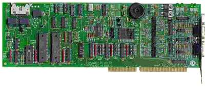
This multifunction card contains a watchdog timer, two RS422/485 serial communications ports, and an internal temperature monitor and computer voltage monitor. This is a full-length card that installs in “long” expansion slots of IBM PC/XT/AT and compatible computers. The following paragraphs describe functions provided.
Watchdog
It’s a fact of life that computers can fail. If a computer fails it can cause catastrophic damage. There are two methods to reduce risk of computer failure; (a) redundancy and (b) a watchdog circuit. Neither method offers 100% assurance but both of these methods reduce risk or consequences of failure. Redundancy, a duplication of computer circuitry, is very expensive. On the other hand, ACCES’ Watchdog card offers excellent protection from temporary malfunctions at very low cost.
The watchdog timer provides means for automatic computer reset in case of processor failure, faulty programs, electrical noise, and some component failures. The circuit works as follows: A countdown timer is periodically loaded by the application program. The application program must communicate with the watchdog circuit at prescribed intervals. If this communication (“prompt”) is missed, the Watchdog counter is not updated, reaches zero, and provides an output that can be used to reset the computer. If the failure was temporary, proper operation is resumed. If, however, the failure is persistent, the Watchdog will continuously reset the computer. The more frequently the computer is prompted (and shorter Watchdog time selected), the less time a faulty computer has to cause damage.
Implementation of this watchdog procedure can be accomplished by your application program, by AUTOEXEC.BAT, or by other appropriate software.
A type 8254 counter/timer chip is used in the Watchdog circuit. The clock source for this chip is 225 HZ derived from a crystal oscillator on the card and is independent of the computer clock. The watchdog time-out is software programmable from 5 mSec to 291 seconds.
The address for the Watchdog circuit is completely independent of the Serial Communication ports addresses. It is DIP switch selectable anywhere within the I/O address range 000 to 3FF hex.
Counter/Timer
A type 8254 counter/timer chip is used in the Watchdog circuit. The 8254 counter/timer chip contains three 16-bit counters and the clock source is a crystal oscillator on the card that is independent of the computer clock. Counter/Timers 1 and 2 are used by the Watchdog circuit. If timeout periods of 25 milliseconds or greater are desired, then counter/timer 2 is the only one used and placement of a jumper applies 225 Hz pulses to that counter. If timeout periods of less than 25 milliseconds are desired, then you can place a jumper that connects the output of counter/timer 1 to counter/timer 2 and a DIP switch permits selection of crystal-controlled clock frequencies of 3.6 KHz or greater. The watchdog time-out is programmable from 5msec to 291 seconds. Counter/timer 0 is available for general purpose use. If not required for the Watchdog time-out period, counter/timer 1 is also available.
Status Register
An ambient-temperature sensing circuit and a voltage monitor circuit are included on the card. Outputs of these circuits as well as watchdog and relay-state functions are provided by a read-only Status Register. If any of the items monitored exceeds preset limits, data are loaded into the Status Register and an Interrupt can be generated.
Temperature Monitor
The temperature monitor circuit compares the output of an LM334 temperature sensor with a preset DC voltage level. The output of the comparator circuit can be read at bit 0 of the Status Register. A “1” in that bit position indicates that temperature is 60oC or less and a “0” at that bit position indicates that the temperature is above 60oC.
There is hysteresis in the sensor. The trip point from “1” to “0” is approximately 50°C while the change from “0” to “1” occurs at about 46°C.
Voltage Monitor
The four computer power supplies (+5V, -5V, +12V, and -12V) are monitored. Three data bits in the Status Register provide information. If those voltages are within tolerance, the state of those three data bits so signifies. If one or more is more than 7% outside of their nominal values, then two or more of those three bits indicate that condition plus also indicates whether the out-of-tolerance voltage(s) is high or low.
Watchdog Counter/Timer Output State
Two bits of the Status Register indicate the state of the counter/timer output and provide a readback of the relays respectively. This is useful at computer initialization because the watchdog function can be tested without actually changing the state of the relays.
Serial Interfaces
The Serial Interface functions of the WDG-2S card, COM-A and COM-B, can be used for either RS422 communications or RS485 communications. (The RS485 specification allows multiple transmitters and receivers to communicate over a two-wire “party line” bus.) Opto-isolators are incorporated on the card to provide isolation from common mode voltage that is present on the Tx, Rx, RTS, and CTS communications lines.
Type 16550 buffered UART’s are used as the Asynchronous Communication Element (ACE). Use of the same ACE as used in IBM original equipment makes the cards 100% compatible with existing programs when the base address is set as either COM-1 or COM-2. However, use of the Serial Interface is not restricted to COM-1 or COM-2 only. Different addresses can be selected anywhere within the I/O address range 100-3FF hex.
An on-board crystal oscillator permits precise software selection of baud rate from 50 to 56K.
The output transceiver used, type 75176, is capable of driving extremely long communication lines at high baud rates. It can drive 60 mA on balanced lines and can receive input signals as low as 200 mV amplitude superimposed on common mode noise of maximum -7V/+12V. In case of communication conflict, the transceivers feature thermal shutdown.
The communication lines are loaded at the receiver and biased at the transmitter. Also, an on-board DC-DC converter provides isolated power to the transceiver and opto-isolators are provided in the serial I/O lines.
Two LED indicators are provided in each serial Interface circuit. These LED’s blink when there is activity on the transmitting and receiving lines and are useful for problem diagnosis.
In addition to dual, differential Transmit and Receive lines, single-ended, buffered RTS and CTS lines are provided on the I/O connector. The RTS line can be used to control the Transmitter and Receiver. The CTS line can be used to check for proper installation of the communication cable. To check for proper cable connection, introduce +5VDC to the CTS line on the cable side of the connector. Then read the CTS bit by software. Signal ground and +5 VDC are available at the I/O connector.
Full duplex, half duplex, or simplex configuration can be selected by jumper options.
Modified-COTS (MCOTS) Customization
ACCES can tailor any standard product to your precise requirements — electrical, mechanical, firmware, environmental, or connector-level. Common MCOTS options include alternate I/O ranges, isolation enhancements, firmware changes, private labeling, conformal coating, extended temperature operation, ruggedized enclosures, and military-grade components. If this product is close but not a perfect fit, our engineering team can deliver a rapid-turn MCOTS variant with minimal NRE and dependable, Made-in-USA quality.
Downloads
Manuals
Software
- WDG-2S Software Package (Last Uploaded 2025-02-06)
Drivers and Downloads
Full list of available Downloads: Software Packages, Drivers, Manuals, and other documents
Information about our Free Software packages:
ACCES is proud to provide a full suite of software support with every Data Acquisition product. We are committed to supporting the most popular operating systems and platforms for our customers. Currently we are actively supporting 7 -> 11, both 32 & 64 bit, including “Server 2008,” “Embedded,” and “Compact” flavors for all plug-and-play products including PCI, PCI Express, USB, and more. Many products continue to ship with support for additional operating systems such as DOS, Windows 95, 98, Me, NT4, 2000, and XP.
Samples
Among the software we deliver with our products are sample programs in a wide variety of programming languages. These samples are used to demonstrate the software interfaces to our products — and many can be used as-is in your production environments, or to test functionality of the devices out-of-the-box. We’re currently actively supporting sample programs in Microsoft Visual C#, and Delphi, with many devices including samples in Visual Basic (5 and .NET), Visual C/C++, and Borland C/C++ 3.1 for DOS. Additionally we provide National Instruments LabVIEW compatible DLLs and many demonstration VIs for our devices.
Drivers
Drivers for various operating systems are also provided, including active support for Windows 7 -> 11 — all in both 32-bit and 64-bit flavors, and including consumer, server, and embedded varieties — as well as the 2.6 and newer Linux kernels and recent OSX / macOS versions. Many products continue to ship with driver support for Windows 95, 98, Me, NT4, Windows 2000, XP, and more, but support for these operating systems is considered deprecated.
Setup Programs and Utilities
Our Data Acquisition devices also include a graphical setup utility that walks you through the process of configuring any option jumpers or switches on the device, as well as explaining a little about the various connectors present.
Many devices also include utility programs – little tools to make your use of the device easier, such as EWriter, a program that allows you to read and write data in the user-accessible EEPROM locations on all our USB data acquisition products; or WinRISC, a “Really Incredibly Simple Communications” terminal program that lets you get started instantly with serial devices.
“Register Level” Documentation
Besides all this software in all these languages and operating systems ACCES has a policy of open and transparent development: none of our lowest-level “register” interfaces are hidden from you — we document every register in every bus card, every command in every serial board, and every usb control transfer in every USB Data Acquisition board. These lowest-level interfaces allow you to develop for our products in ANY operating system or language, regardless of our actively supporting it or having a driver for it. We have customers actively developing in ADA, Android, Python, Java, MATLAB, Solaris, and more, just by referring to our complete low-level interface documentation! And we provide the full source code to all of our drivers, regardless of operating system, to give you an even bigger head start in your own development tasks.
No Fees or Royalties
All of this software is provided at no additional charge, and is licensed under any of a variety of flexible — and royalty free — options. Check out our software license explanation if you’d like more information.
AIOSerial/VxWorks
ACCES has successfully partnered with Wind River to bring our entire line of PCI and PCI Express Serial Communication cards to VxWorks 7! All ACCES plug-and-play serial cards are now supported with our VxWorks driver, including RS232, RS422, RS485 (2- and 4-wire) and baud rates up to 10Mbps.
Designed as an update to the existing vxbPciNs16550Sio.c driver, we’ve added support for ×8 baud rates, proper handling of the unique register location of the 4th port in the Pericom PI7C9X7954 UART, and configuring the serial protocol from your application software.
With this driver suite all ACCES PCI, PCI Express, PCI Express Mini Card, M.2, PCI-104, PCIe/104, and all related “PCI Style” plug-and-play serial cards will detect and install as standard VxWorks SIO ports.
Watchdog Timer
- Time-out: Software selectable from 5 mSec to 291 Sec in 5 mSec increments.
- Output Pulse Width: 4 msec.
- Clock: Selectable from 255 Hz, 3.6864 kHz, 28.8 kHz, 230 kHz, and 1843 kHz, crystal controlled.
- Address: Continuously mappable within 000 to 3FF hex I/O range.
- Relay Output: Contacts rated at 250 mA at up to 24VDC.
Supply Monitor
- Computer Voltages: +5 V, -5V, +12V, and -12V are monitored
Any voltage exceeding 7% beyond nominal value generates a Status Interrupt Request - Temperature: Factory preset at 50°C ±2°C Adjustable.
- Interrupts: Jumper selectable from IRQ2 through IRQ7, IRQ10 through IRQ12, IRQ14 or IRQ15
- Alternate Output: Can be read at BASE ADDRESS + 4.
Communications Interface
- I/O Connection: 9-pin male D-sub connectors.
- Serial Ports: Two shielded male D-sub 9-pin connectors compatible with RS-422 and RS-485 specifications.
- Input Isolation: 60 Volts, signal to ground and signal to signal.
- Character length: 5, 6, 7, or 8 bits.
- Parity: Even, odd or none.
- Stop Interval: 1, 1.5, or 2 bits.
- Serial Data Rates: 50 to 56K (Faster or custom rates available), Asynchronous, Type 16550 buffered UART.
- Address: Continuously mappable within 000 to 3FF (hex) range of AT I/O bus addresses.
RS422/RS485 Differential Communication Mode
- Multipoint: Compatible with RS422 and RS485 specifications. Up to 32 drivers and receivers allowed on line. Serial communications ACE used is type 16550. Driver/Receivers used are type 75ALS180.
- Receiver Input Sensitivity: +200 mV, differential input.
- Common Mode Rejection: +12V to -7V
- Transmitter Output Drive Capability: 60 mA, with thermal shutdown.
Environmental
- Operating Temperature: 0 to +60 degree C.
- Storage Temperature: -50 to +120 degree C.
- Humidity: 10% to 90% non condensing.
- Size: 13.3 inches. (330mm)
Power Requirements
- +5 VDC at 420 mA, 500 mA maximum
Regulatory Compliance
- This product is in full compliance with CE requirements.
| Model | Description | Price (USD) | |
|---|---|---|---|
| WDG-2S | This multifunction card contains a watchdog timer, two RS422/485 serial communications ports, and an internal temperature monitor and computer voltage monitor. This is a full-length card that installs in “long” expansion slots of IBM PC/XT/AT and compatible computers. The following paragraphs describe functions provided. WatchdogIt’s a fact of life that computers can fail. If a computer fails it can cause catastrophic damage. There are two methods to reduce risk of computer failure; (a) redundancy and (b) a watchdog circuit. Neither method offers 100% assurance but both of these methods reduce risk or consequences of failure. Redundancy, a duplication of computer circuitry, is very expensive. On the other hand, ACCES’ Watchdog card offers excellent protection from temporary malfunctions at very low cost. The watchdog timer provides means for automatic computer reset in case of processor failure, faulty programs, electrical noise, and some component failures. The circuit works as follows: A countdown timer is periodically loaded by the application program. The application program must communicate with the watchdog circuit at prescribed intervals. If this communication (“prompt”) is missed, the Watchdog counter is not updated, reaches zero, and provides an output that can be used to reset the computer. If the failure was temporary, proper operation is resumed. If, however, the failure is persistent, the Watchdog will continuously reset the computer. The more frequently the computer is prompted (and shorter Watchdog time selected), the less time a faulty computer has to cause damage. Implementation of this watchdog procedure can be accomplished by your application program, by AUTOEXEC.BAT, or by other appropriate software. A type 8254 counter/timer chip is used in the Watchdog circuit. The clock source for this chip is 225 HZ derived from a crystal oscillator on the card and is independent of the computer clock. The watchdog time-out is software programmable from 5 mSec to 291 seconds. The address for the Watchdog circuit is completely independent of the Serial Communication ports addresses. It is DIP switch selectable anywhere within the I/O address range 000 to 3FF hex. Counter/TimerA type 8254 counter/timer chip is used in the Watchdog circuit. The 8254 counter/timer chip contains three 16-bit counters and the clock source is a crystal oscillator on the card that is independent of the computer clock. Counter/Timers 1 and 2 are used by the Watchdog circuit. If timeout periods of 25 milliseconds or greater are desired, then counter/timer 2 is the only one used and placement of a jumper applies 225 Hz pulses to that counter. If timeout periods of less than 25 milliseconds are desired, then you can place a jumper that connects the output of counter/timer 1 to counter/timer 2 and a DIP switch permits selection of crystal-controlled clock frequencies of 3.6 KHz or greater. The watchdog time-out is programmable from 5msec to 291 seconds. Counter/timer 0 is available for general purpose use. If not required for the Watchdog time-out period, counter/timer 1 is also available. Status RegisterAn ambient-temperature sensing circuit and a voltage monitor circuit are included on the card. Outputs of these circuits as well as watchdog and relay-state functions are provided by a read-only Status Register. If any of the items monitored exceeds preset limits, data are loaded into the Status Register and an Interrupt can be generated. Temperature MonitorThe temperature monitor circuit compares the output of an LM334 temperature sensor with a preset DC voltage level. The output of the comparator circuit can be read at bit 0 of the Status Register. A “1” in that bit position indicates that temperature is 60oC or less and a “0” at that bit position indicates that the temperature is above 60oC. There is hysteresis in the sensor. The trip point from “1” to “0” is approximately 50°C while the change from “0” to “1” occurs at about 46°C. Voltage MonitorThe four computer power supplies (+5V, -5V, +12V, and -12V) are monitored. Three data bits in the Status Register provide information. If those voltages are within tolerance, the state of those three data bits so signifies. If one or more is more than 7% outside of their nominal values, then two or more of those three bits indicate that condition plus also indicates whether the out-of-tolerance voltage(s) is high or low. Watchdog Counter/Timer Output StateTwo bits of the Status Register indicate the state of the counter/timer output and provide a readback of the relays respectively. This is useful at computer initialization because the watchdog function can be tested without actually changing the state of the relays. Serial InterfacesThe Serial Interface functions of the WDG-2S card, COM-A and COM-B, can be used for either RS422 communications or RS485 communications. (The RS485 specification allows multiple transmitters and receivers to communicate over a two-wire “party line” bus.) Opto-isolators are incorporated on the card to provide isolation from common mode voltage that is present on the Tx, Rx, RTS, and CTS communications lines. Type 16550 buffered UART’s are used as the Asynchronous Communication Element (ACE). Use of the same ACE as used in IBM original equipment makes the cards 100% compatible with existing programs when the base address is set as either COM-1 or COM-2. However, use of the Serial Interface is not restricted to COM-1 or COM-2 only. Different addresses can be selected anywhere within the I/O address range 100-3FF hex. An on-board crystal oscillator permits precise software selection of baud rate from 50 to 56K. The output transceiver used, type 75176, is capable of driving extremely long communication lines at high baud rates. It can drive 60 mA on balanced lines and can receive input signals as low as 200 mV amplitude superimposed on common mode noise of maximum -7V/+12V. In case of communication conflict, the transceivers feature thermal shutdown. The communication lines are loaded at the receiver and biased at the transmitter. Also, an on-board DC-DC converter provides isolated power to the transceiver and opto-isolators are provided in the serial I/O lines. Two LED indicators are provided in each serial Interface circuit. These LED’s blink when there is activity on the transmitting and receiving lines and are useful for problem diagnosis. In addition to dual, differential Transmit and Receive lines, single-ended, buffered RTS and CTS lines are provided on the I/O connector. The RTS line can be used to control the Transmitter and Receiver. The CTS line can be used to check for proper installation of the communication cable. To check for proper cable connection, introduce +5VDC to the CTS line on the cable side of the connector. Then read the CTS bit by software. Signal ground and +5 VDC are available at the I/O connector. Full duplex, half duplex, or simplex configuration can be selected by jumper options. | $406.00 |