PCI-DIO-48S/48/24S PCI Digital I/O Cards w/CoS IRQ
Features
- Universal PCI, PCI-X, 3.3V and 5V compatible
(PCI-Express versions available) - 24 or 48 bits of digital I/O
- Interrupt generation on input change-of-state (“S” versions)
- All I/O lines buffered on the card
- I/O buffers can be enabled/disabled under program control
- Four- and eight-bit ports independently selectable for I/O
- Pull-ups on I/O lines
- +5V supply available to the user
- 50-pin headers are compatible with industry standard I/O racks like Gordos, Opto-22, Potter & Brumfield, etc.
- No base address or IRQ switches to set
- RoHS Available. Please contact us for ordering information
- Support for Wind River VxWorks (call for ordering information)
Price range: $478.00 through $698.00
In StockDescription
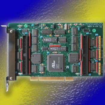
The PCI-DIO-24S/48/48S are 24- and 48-bit parallel digital input/output cards designed for use in PCI-Bus computers. The card is 6.9 inches (175 mm) long and may be installed in any 5-volt PCI slot in IBM and compatible computers.
The cards use 50-pin headers on the face of the board. The 24S card is simply a depopulated 48S card. Ribbon cables (see the ORDERING INFO tab) must be routed through a cutout in the card mounting bracket, and secured using the provided strain relief mechanism.
For solutions that don’t require internal access to the chassis to make connections to the I/O card, consider our model PCI-DIO-48JPS product family, which uses a 68 pin SCSI pin-in-socket connector on the card mounting bracket.
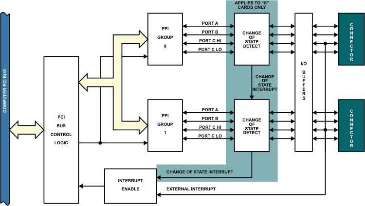
The cards contain two Programmable Peripheral Interface chips type 8255-5 (PPI) to provide computer interface to the 48 I/O lines. Each PPI provides three 8-bit ports A, B and C. Each 8-bit port can be software configured to function as either inputs or latched outputs. Port C can also be configured with four inputs and four output latches.
Each I/O line is buffered and capable of sourcing 15 mA or sinking 24 mA (64 mA on request). Tristate I/O line buffers are configured automatically by the hardware logic for input or output use according to a direction control signal from the control register in the PPI. Pull-ups on the card assure that there are no erroneous outputs at power up until the card is initialized by system software.
These cards use one address space, and occupy 16 consecutive register locations. When the card is first installed, Windows will detect it as new hardware and assign it an IRQ number and base address. There are no switches to set or base addresses to assign, making it easy to use. You cannot set or change the card’s base address, you can only determine what the system has assigned. The PCI Bus supports 64K of I/O address space so your card’s address may be located anywhere in the 0000 to FFFF range.
INTERRUPTS
The distinguishing feature for the “48S” model is that the state of all inputs can be monitored and if one or more of the bits change states, a latched interrupt request can be generated. Therefore it is not necessary to use software polling on the inputs to detect a change of state condition. The change-of-state interrupt is enabled by a software write command to an interrupt-enable register. Once latched, the change-of-state interrupt can be cleared by a software write.
The C3 bit on either 24-bit port can be used as an external interrupt to the computer if interrupt enable (IEN) jumpers are installed. When C3 is level triggered, an interrupt is requested. Interrupts from the two ports are OR’ed together with any change-of-state interrupt. The interrupts are assigned by the system.
ACCESSORIES
Available accessories include a wide variety of cables and screw terminal boards for quick and easy connectivity.

Modified-COTS (MCOTS) Customization
ACCES can tailor any standard product to your precise requirements — electrical, mechanical, firmware, environmental, or connector-level. Common MCOTS options include alternate I/O ranges, isolation enhancements, firmware changes, private labeling, conformal coating, extended temperature operation, ruggedized enclosures, and military-grade components. If this product is close but not a perfect fit, our engineering team can deliver a rapid-turn MCOTS variant with minimal NRE and dependable, Made-in-USA quality.
Downloads
Manuals
Software
- PCI-DIO-48S Family Software Package ( -- Last Uploaded 2025-05-07)
Drivers and Downloads
Full list of available Downloads: Software Packages, Drivers, Manuals, and other documents
Information about our Free Software packages:
ACCES is proud to provide a full suite of software support with every Data Acquisition product. We are committed to supporting the most popular operating systems and platforms for our customers. Currently we are actively supporting 7 -> 11, both 32 & 64 bit, including “Server 2008,” “Embedded,” and “Compact” flavors for all plug-and-play products including PCI, PCI Express, USB, and more. Many products continue to ship with support for additional operating systems such as DOS, Windows 95, 98, Me, NT4, 2000, and XP.
Samples
Among the software we deliver with our products are sample programs in a wide variety of programming languages. These samples are used to demonstrate the software interfaces to our products — and many can be used as-is in your production environments, or to test functionality of the devices out-of-the-box. We’re currently actively supporting sample programs in Microsoft Visual C#, and Delphi, with many devices including samples in Visual Basic (5 and .NET), Visual C/C++, and Borland C/C++ 3.1 for DOS. Additionally we provide National Instruments LabVIEW compatible DLLs and many demonstration VIs for our devices.
Drivers
Drivers for various operating systems are also provided, including active support for Windows 7 -> 11 — all in both 32-bit and 64-bit flavors, and including consumer, server, and embedded varieties — as well as the 2.6 and newer Linux kernels and recent OSX / macOS versions. Many products continue to ship with driver support for Windows 95, 98, Me, NT4, Windows 2000, XP, and more, but support for these operating systems is considered deprecated.
Setup Programs and Utilities
Our Data Acquisition devices also include a graphical setup utility that walks you through the process of configuring any option jumpers or switches on the device, as well as explaining a little about the various connectors present.
Many devices also include utility programs – little tools to make your use of the device easier, such as EWriter, a program that allows you to read and write data in the user-accessible EEPROM locations on all our USB data acquisition products; or WinRISC, a “Really Incredibly Simple Communications” terminal program that lets you get started instantly with serial devices.
“Register Level” Documentation
Besides all this software in all these languages and operating systems ACCES has a policy of open and transparent development: none of our lowest-level “register” interfaces are hidden from you — we document every register in every bus card, every command in every serial board, and every usb control transfer in every USB Data Acquisition board. These lowest-level interfaces allow you to develop for our products in ANY operating system or language, regardless of our actively supporting it or having a driver for it. We have customers actively developing in ADA, Android, Python, Java, MATLAB, Solaris, and more, just by referring to our complete low-level interface documentation! And we provide the full source code to all of our drivers, regardless of operating system, to give you an even bigger head start in your own development tasks.
No Fees or Royalties
All of this software is provided at no additional charge, and is licensed under any of a variety of flexible — and royalty free — options. Check out our software license explanation if you’d like more information.
Custom Software
ACCES also offers Custom Software Services for our products. Our prices are unbelievably low, often as inexpensive as free! If you need something tweaked to support your needs, or an entire enterprise application developed from scratch, it is definitely worth your time to inquire with us, first.
Further information about available ACCES Software:
Redistributing Windows Drivers
A list of ACCES drivers and the files that compose them under different versions of Windows, so you can easily redistribute ACCES cards and drivers.
aioWDM.VxWorks
ACCES has successfully partnered with Wind River to bring our entire line of PCI and PCI Express DAQ cards to VxWorks 7!
VxWorks 7 VxBus Gen 2 drivers, with easy-to-use API-libraries, are available for this product, including full source and sample code.
Designed to be compatible with our AIOWDM.dll Windows driver & API, this kernel module adds zero% CPU-cycle overhead to your VxWorks runtimes while allowing the lowest-latency hardware register access possible.
You can find more information about our VxWorks libraries and services on our Wind River Silver Partner page.

Digital Inputs (TTL Compatible)
- Logic High: 2.0 to 5.0 VDC
- Logic Low: -0.5 to +0.8 VDC
- Input Load (Hi): 20 uA
- Input Load (Lo): -200 uA
Digital Outputs
- Logic High: 2.0 VDC min., source 32 mA
- Logic Low: 0.55 VDC max., sink 64 mA
Power Output
- +5 VDC from computer bus (ext. 1A fast-blow fuse recommended)
Power Required
- +5 VDC at 200 mA typical
Size
- 6.9″ (175 mm) long
Environmental
- Operating Temperature: 0o to 60o C
- Storage Temperature: -50o to +120o C
- Humidity: 0 to 90% RH, non-condensing
This product is in full compliance with CE requirements.
| Model | Description | Price (USD) | |
|---|---|---|---|
| PCI-DIO-24S | PCI 24 bit Digital I/O Card, One 50-pin IDC Connector, COS IRQ, | $478.00 | |
| PCI-DIO-48 | PCI 48 bit Digital I/O Card, Two 50-pin IDC Connectors | $558.00 | |
| PCI-DIO-48S | PCI 48 bit Digital I/O Card, Two 50-pin IDC Connectors, CoS IRQ | $698.00 |
| Accessories | |
|---|---|
| STB-50 | DIN-rail mountable screw terminal board for 50 pin header type connector $44 |
| CAB50F-6 | 50 pin ribbon cable with female header connectors, 6 feet long $30 |
| STB-48CH | 48 digital I/O single screw terminal board $149 |
| IIB-24 | 24 channel optical isolater board for each 50 pin header $149 |
| ROB-24 | 24 channel electromechanical relay card for each 50 pin header |
| Model Options: | |
| -LV | Factory option for 3.3V LVTTL signaling on digital connectors |
| -M | Molex PC-style connector for maximum 5V VCCIO current sourcing capability |
| -RoHS | RoHS compliant version |
| -T | Extended temperature (-40°C to +85°C) |

