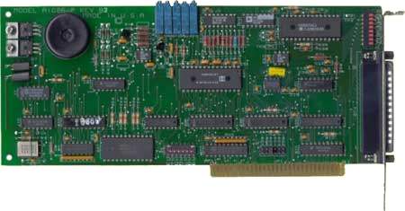
AD12-8G ISA Bus 12-Bit 8-Input Programmable-Gain A/D Converter and Counter/Timer Card
Features
- Eight single-ended or differential analog inputs
- 12-bit resolution
- Nine software programmable voltage ranges
- Programmable scan rate
- Foreground/background operation
- Three 16-bit counter/timers for event counting, pulse and waveform generation, and frequency measurement.
- Seven bits of digital I/O
- Can assert interrupts
- Designed, made, supported, and manufactured in the USA
Call
In StockDescription
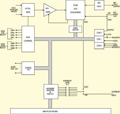
ANALOG INPUTS
COUNTER/TIMER
DIGITAL I/O
Customized Analog I/O (MCOTS Options)
ACCES specializes in modified-COTS analog I/O. We can customize voltage ranges, sampling rates, filtering, isolation, gain stages, calibration profiles, firmware behavior, connector styles, and environmental ruggedness. If your analog requirements are unique, we excel at delivering tailored MCOTS analog hardware quickly and cost-effectively.
Downloads
Manuals
Software
- AD12-8G Software Package (Last Uploaded 2025-02-06)
Drivers and Downloads
Full list of available Downloads: Software Packages, Drivers, Manuals, and other documents
Information about our Free Software packages:
ACCES is proud to provide a full suite of software support with every Data Acquisition product. We are committed to supporting the most popular operating systems and platforms for our customers. Currently we are actively supporting 7 -> 11, both 32 & 64 bit, including “Server 2008,” “Embedded,” and “Compact” flavors for all plug-and-play products including PCI, PCI Express, USB, and more. Many products continue to ship with support for additional operating systems such as DOS, Windows 95, 98, Me, NT4, 2000, and XP.
Samples
Among the software we deliver with our products are sample programs in a wide variety of programming languages. These samples are used to demonstrate the software interfaces to our products — and many can be used as-is in your production environments, or to test functionality of the devices out-of-the-box. We’re currently actively supporting sample programs in Microsoft Visual C#, and Delphi, with many devices including samples in Visual Basic (5 and .NET), Visual C/C++, and Borland C/C++ 3.1 for DOS. Additionally we provide National Instruments LabVIEW compatible DLLs and many demonstration VIs for our devices.
Drivers
Drivers for various operating systems are also provided, including active support for Windows 7 -> 11 — all in both 32-bit and 64-bit flavors, and including consumer, server, and embedded varieties — as well as the 2.6 and newer Linux kernels and recent OSX / macOS versions. Many products continue to ship with driver support for Windows 95, 98, Me, NT4, Windows 2000, XP, and more, but support for these operating systems is considered deprecated.
Setup Programs and Utilities
Our Data Acquisition devices also include a graphical setup utility that walks you through the process of configuring any option jumpers or switches on the device, as well as explaining a little about the various connectors present.
Many devices also include utility programs – little tools to make your use of the device easier, such as EWriter, a program that allows you to read and write data in the user-accessible EEPROM locations on all our USB data acquisition products; or WinRISC, a “Really Incredibly Simple Communications” terminal program that lets you get started instantly with serial devices.
“Register Level” Documentation
Besides all this software in all these languages and operating systems ACCES has a policy of open and transparent development: none of our lowest-level “register” interfaces are hidden from you — we document every register in every bus card, every command in every serial board, and every usb control transfer in every USB Data Acquisition board. These lowest-level interfaces allow you to develop for our products in ANY operating system or language, regardless of our actively supporting it or having a driver for it. We have customers actively developing in ADA, Android, Python, Java, MATLAB, Solaris, and more, just by referring to our complete low-level interface documentation! And we provide the full source code to all of our drivers, regardless of operating system, to give you an even bigger head start in your own development tasks.
No Fees or Royalties
All of this software is provided at no additional charge, and is licensed under any of a variety of flexible — and royalty free — options. Check out our software license explanation if you’d like more information.
Custom Software
ACCES also offers Custom Software Services for our products. Our prices are unbelievably low, often as inexpensive as free! If you need something tweaked to support your needs, or an entire enterprise application developed from scratch, it is definitely worth your time to inquire with us, first.
Further information about available ACCES Software:
Redistributing Windows Drivers
A list of ACCES drivers and the files that compose them under different versions of Windows, so you can easily redistribute ACCES cards and drivers.
Analog Inputs
- Number of Channels: Eight differential or single- ended, individually DIP switch selectable for S.E. or Diff.
- Voltage Range: Programmable, ±5V (default), ±10V, ±0.5V, ±0.05V, ±0.01V, 0-10V, 0-1V, 0-0.1V, 0-0.02V.
- Overvoltage Protection: ±30 VDC.
- Input Impedance: 10 Megohm or 125 nA at 25°C.
- Common Mode Rejection Ratio: 90 db when gain = 1; 125 db when gain = 100.
- Multiplexer/Sample and Hold Settle Time: When gain = 1 : 30 µSec; When gain = 100 : 95 µSec
- Overall Accuracy: ±0.05% of full scale.
- Linearity: ±1 LSB.
- Resolution: 12 bit binary.
- A/D Trigger Source: Software selectable, external trigger, programmable timer, or program command.
- Conversion Time: 35 µSec max., 25 µSec typical.
- Temperature Coefficient: ±10 µV per °C zero stability. ±25 µV per °C gain stability.
Digital Inputs/Outputs
Inputs
-
- Logic Low: 0 to 0.4V at 8 mA sink.
- Logic High: 2.4 to 5.0V at 0.4 mA source.
Outputs
-
- Logic Low: 0 to 0.4V at 8 mA sink.
- Logic High: 2.4 to 5.0V at 0.4 mA source.
Counter Timer
- Type: 8254 programmable interval timer, three 16-bit counters.
- Drive Capability: 5 LSTTL loads (2.2 mA at 0.45 VDC).
- Input Load (Gate and Clock): ±10 µA, TTL/CMOS compatible.
- Input Clock Frequency:10 MHz max.
- Active Count Edge:Negative edge.
- Clock Pulse Width: 50 nSec high / 50 nSec low, min.
Interrupts
- Level: Jumper selectable, levels 2-7.
- Enable/Disable: Via software. (INTE bit of Control Register. Service routines should acknowledge and re-enable interrupts.)
- Source: End of conversion or user application.
Environmental
- Operating Temperature Range: 0° to 60°C.
- Storage Temperature Range: -40° to +100°C.
- Humidity: 0 to 95% RH, non-condensing.
Power Required
- +5 VDC at 180 mA max.
- +12 VDC at 500 mA max.
Size
- 9.0 inches long. (229mm)
- Requires full-size slot.
Regulatory Compliance
- This product is in full compliance with CE requirements.
- MOQ’s may be required.
| Model | Description | Price (USD) | |
|---|---|---|---|
| AD12-8G | ISA Bus 12-Bit 8-Input Programmable Gain A/D Converter and Counter/Timer Card | Call |