
M.2 Takes On Smaller Footprints and Bigger I/O Demands
Modern embedded systems need compact, rugged I/O without locking every sensor, actuator, or interface decision into the carrier board.
BY JOHN HENTGES, ACCES I/O PRODUCTS, INC.
Embedded computers have become smaller much faster than the physical world they monitor and control. A compact computer-on-module or single-board computer can now provide multicore processing, GPU or AI acceleration, high-speed storage, graphics, networking, and substantial memory. The sensors and actuators around it, however, still require analog front ends, digital level translation, isolation, serial transceivers, counters, protection, and physical connectors.
That mismatch makes I/O expansion a decisive part of the system architecture. The processor may fit in the palm of a hand, yet a conventional PCI Express card or stackable I/O assembly can dominate the enclosure. Integrating every I/O circuit onto a custom carrier board reduces volume, but it also commits the design to requirements that may change before production or after hundreds of systems are already in service.
The I/O problem did not shrink
Full-custom carrier boards are efficient when requirements are stable and production volume can justify the engineering, validation, and inventory costs. They are less attractive when a late requirement adds another encoder, an isolated RS-485 channel, a different analog range, or several protected outputs. A seemingly modest I/O change can force a schematic revision, PCB layout, prototype build, compliance review, software update, and another production qualification cycle.
Large plug-in cards preserve flexibility but consume valuable space. Stackable systems are mechanically robust, but their board area, connector stack, and service access may be difficult to accommodate in a mobile, vehicle, robotic, or tightly packaged test system. External USB or Ethernet I/O can be the right answer when distance or distribution matters, but an external enclosure and cable are unnecessary overhead when the I/O belongs inside the computer.
For PCIe-based I/O, M.2 occupies the useful middle ground: a compact, replaceable module connected directly to the host, with PCI Express performance and software behavior, but without the envelope of a desktop card or a board stack.
A better boundary between custom and COTS
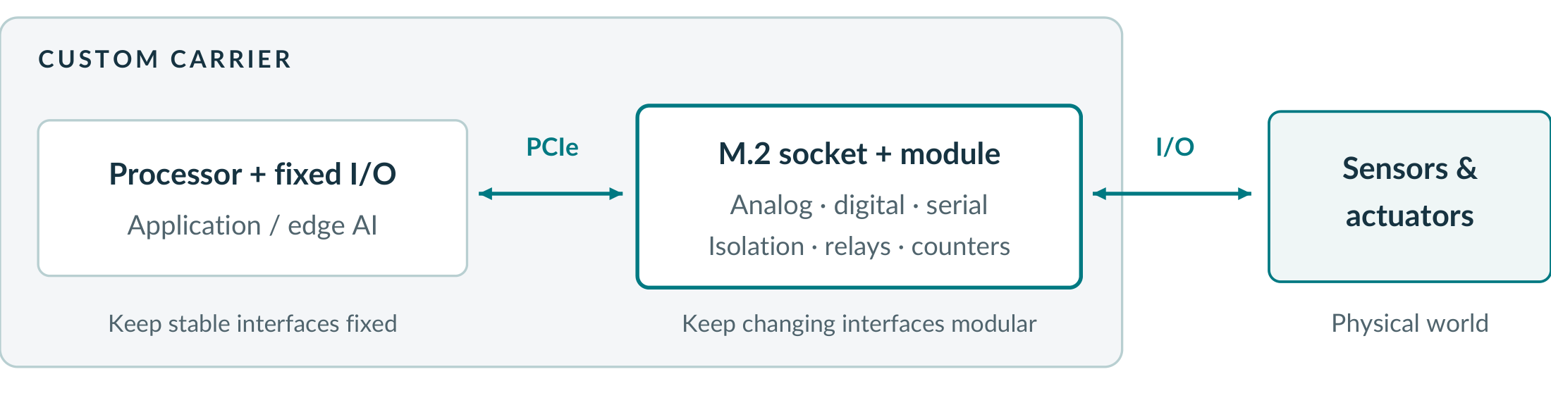
The practical design question is not simply “custom or commercial off-the-shelf?” It is where to place the boundary between them. A custom carrier can contain the interfaces that are certain to remain fixed while one or more M.2 sockets accept the functions most likely to vary. That approach lets a common computing platform support several product configurations, accommodates changes without redesigning the carrier, and postpones irreversible I/O decisions until the requirements are proven.
For low- and medium-volume systems, the M.2 module may remain the production solution. At higher volumes, it can serve as a working prototype of circuitry that is later integrated onto the carrier. In either case, real hardware is available early enough for firmware and application development, instead of forcing software teams to wait for the final carrier-board spin.
M.2 is a form factor, not a synonym for NVMe
M.2 is familiar because of its widespread use for solid-state storage, but NVMe is a storage protocol, not the definition of the connector. The PCI-SIG M.2 specification defines a family of module sizes, key positions, mechanical arrangements, and electrical interfaces. Depending on the host and keying, an M.2 socket may expose PCI Express, SATA, USB, or other signals.
That distinction matters when specifying industrial I/O. A card that physically fits is not automatically electrically compatible. For PCI Express I/O, the host socket must provide PCIe signals, the keying and standoff must match, adequate power and component clearance must be available, and the system firmware must enumerate a general PCIe endpoint rather than assume that the socket will contain only storage.
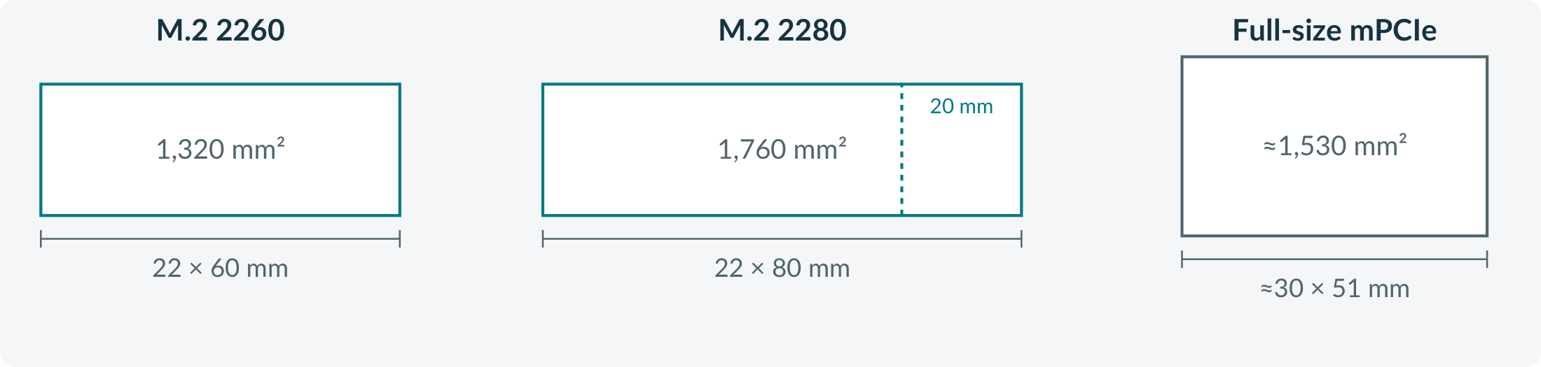
Standard ACCES M.2 I/O modules are 22 mm wide and use a B+M-keyed 2280 format with a breakaway section for 2260 installations. In M.2 nomenclature, 2260 means 22 mm wide by 60 mm long; 2280 means 22 mm by 80 mm. Compared with a full-size mPCIe card at approximately 30 mm by 51 mm, the 2260 format uses less board area, while 2280 uses somewhat more. The important advantage is therefore not that every M.2 card is smaller than mPCIe, but that M.2 offers a narrower shape and selectable length that often fits current embedded-system layouts more efficiently.
Ruggedness is a system property
M.2 modules are retained by a standoff fastener rather than by connector friction alone, but the module is only one part of a rugged design. The external I/O connection, cable mass, strain relief, enclosure, airflow, grounding, and mounting orientation all affect shock, vibration, thermal, and electromagnetic performance.
All ACCES M.2 products use positive-latching board connectors; optional panel-mount cable assemblies help keep external cable loads away from the card edge. Extended-temperature operation is available as an option on all ACCES M.2 cards. Most are rated from -40 °C to +85 °C; M.2-IIRO models are rated from -40 °C to +70 °C because of the electromechanical relays. Conformal coating is also available. Those features make system qualification easier; they do not replace qualification of the complete assembly. Likewise, M.2 should not be treated as hot-swappable unless the host and finished system were explicitly designed for that behavior.
Focused modules put the right I/O near the processor
The limited area of an M.2 module encourages a focused design instead of the “everything board” approach common on larger multifunction cards. The result is less unused circuitry and a closer match between each system variant and its actual I/O.
For measurement and control, the ACCES M.2-AIO16-16FDS family combines up to 16 single-ended or eight differential analog inputs with two 16-bit ADCs that sample simultaneously, four analog outputs, FIFO and DMA transfers, and hardware-paced waveform output on the FDS models. Applications needing fewer analog inputs but more general-purpose digital lines can instead use the M.2-ADIO family, which combines analog input and output with 16 digital I/O lines.
When the requirement is discrete control or timing rather than analog measurement, the M.2-DIO-24X provides 24 high-current LVTTL I/O lines plus FPGA-based pulse, PWM, and frequency generation; input filtering and pulse measurement; event counting; and interrupt generation. Moving those deterministic functions into hardware avoids software polling and reduces dependence on operating-system scheduling latency.
Legacy interfaces have not disappeared merely because the computer is new. Industrial instruments, encoders, motor drives, and controllers still rely heavily on RS-232, RS-422, and RS-485. The M.2-COM-4SM family provides two- or four-port serial configurations with software-selectable protocols, while the isolated M.2-ICM family helps address ground-potential differences and electrically noisy installations.
Other applications need electrical isolation, protected power switching, relay contacts, or dedicated encoder interfaces rather than generic GPIO. The M.2-IDIO family combines isolated inputs with protected solid-state outputs, and the M.2-QUAD-4/8 family provides four or eight 32-bit quadrature-counter channels. The point is not to turn one M.2 socket into a universal instrument. It is to populate that socket with the specific interface the application actually needs.
M.2 connects edge AI to the physical world
Compact edge computers are increasingly used for anomaly detection, predictive maintenance, and other machine-learning applications close to the equipment. The model may run on an embedded x86 or Arm computer, but it cannot directly observe current, temperature, vibration, pressure, relay state, or motion. An M.2 data acquisition (DAQ) module provides that physical interface without requiring an external enclosure or full-size expansion card. Analog inputs capture continuous measurements, digital inputs and counters provide operating context, and FIFO and DMA transfers move the data efficiently into host memory for local analysis.
That does not make the M.2 card itself an AI device. The DAQ hardware acquires accurate, timely signals; the customer’s application supplies the intelligence. Hardware timing, interlocks, and conventional control loops can continue handling deterministic or safety-critical functions while AI analyzes operating histories, recognizes multivariable patterns, forecasts maintenance needs, or recommends higher-level adjustments.
Smaller hardware can also shorten the schedule
An M.2-to-PCIe adapter can place the target I/O module in a development workstation before the embedded carrier is ready. Software teams can exercise drivers, APIs, interrupts, DMA paths, and application logic against production-intent hardware while the mechanical and carrier-board work continues in parallel.
Many ACCES M.2 products also mirror established mPCIe versions, preserving software interfaces and I/O pinouts across the migration. That continuity can matter more than the physical size: it allows proven application code, cabling, test fixtures, and register-level knowledge to move to a newer computing platform with less risk.
In service, an M.2 module can be replaced or changed without replacing the carrier board or dismantling a multi-board stack. Whether the module qualifies as a line-replaceable unit still depends on enclosure access, connectors, procedures, and the rest of the system design, but modular I/O gives the designer the option.
Verify these details before committing to an M.2 I/O design
- Electrical interface: Confirm that the selected socket actually carries PCI Express; “M.2” alone is not sufficient.
- Mechanics: Check keying, 2260/2280 standoff locations, component-height limits, nearby keep-out areas, and cable exit direction.
- Firmware: Verify enumeration of non-storage PCIe endpoints and any BIOS/UEFI controls associated with the socket.
- Power and heat: Compare the module’s 3.3 V demand and dissipation with the host’s slot budget, cooling, and worst-case ambient temperature.
- External I/O: Plan latching connectors, panel mounting, strain relief, grounding, shielding, and isolation as parts of the system, not accessories added at the end.
Preserve flexibility where change is most likely
M.2 does not eliminate custom carrier design, and it is not automatically the right answer for every system. Its value is that it prevents application-specific I/O from being frozen too early. The processor, AI workload, and carrier can follow the computing platform’s lifecycle while analog, digital, serial, isolated, relay, and counter functions remain modular.
For compact industrial, defense, mobile, laboratory, and OEM equipment, that division can reduce engineering effort, shorten the path to working hardware, simplify product variants, and leave room for requirements that have not yet appeared. A broad selection of production-ready M.2 data acquisition and control modules makes the trade practical without forcing one-size-fits-all hardware into every system. It also gives edge-AI applications a direct path to the real-world measurements on which useful models depend.
John Hentges is Director of Software Engineering and Digital Design at ACCES I/O Products. He has spent more than three decades developing data acquisition hardware, drivers, APIs, and application software for industrial, scientific, and embedded systems.
Explore the M.2 I/O range: accesio.com/m-2/