USB DAQ Firmware, 2.0 Release, Major Features
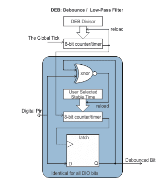 Debouncing provides a way to avoid the vagaries of mechanical contact bounce from confusing your software and users. By commanding the onboard intelligence to monitor the inputs and filter out contact bounce you avoid needing to add low-pass filtering circuits to each of your button and relay digital inputs. Firmware 2.0 allows flexible debouncing time constants from tens of microseconds to hundreds of milliseconds, per bit, compatible with the widest variety of contact closures, on all digital bits of each device.
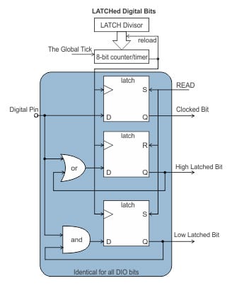 Latching allows your software to relax, and let the onboard intelligence obsess over catching that pulse — and can make noticing shorter pulses trivial instead of virtually impossible. The Firmware 2.0 release can simultaneously perform low-side and high-side latching of all digital inputs, clearing the latches only when your application gets around to reading them. The onboard intelligence can read the digital inputs faster than once every 100 microseconds without consuming any CPU cycles from your host computer.
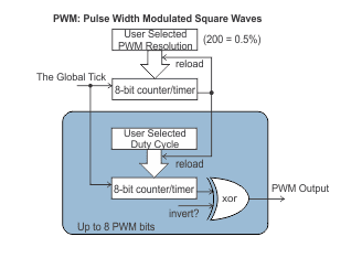 PWM output bits generate square waves, with configurable duty cyle andpolarity. Up to 8 digital outputs can be performing PWM output at the same time, per device.
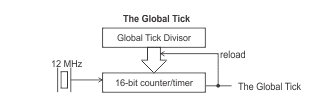 An onboard periodic IRQ generator creates one Global Tick IRQ at a rate you can configure, based on a 16-bit divisor of an internal 12MHz clock. This allows the Global Tick IRQ to occur at rates as slow as 183Hz, or as fast as 10kHz or more. Each Firmware 2.0 feature operates either on every Global Tick, or on a tick derived from a further 8-bit division of this rate.
DEF – power-on defaults stores these divisors, but it only operates when commanded, not per any given tick.
WDG – Watchdog operates on a One Second tick, and counts down your configured timeout period before barking
DEB – Debounced digital inputs use an a local tick and a time constant. You specify what division of the global tick should be used to create the Debounce Tick (divide by 1 through 255). On each Debounce Tick every digital bit on the device is read, and if it has been stable for as many Debounce Ticks as the time constant specifies, updates the “debounced” copy of the digital data.
LATCH – Latched digital inputs also use a local tick, specified as a further 8-bit (1-255) divisor of the global Tick. Each Latch Tick will cause all digital bits to be read, and evaluated for high-or-low, and stored. Reading Latched data provides three different pieces of information for each and every digital bit: the state of the bit at the most recent Latch tick, if the bit has been low since last read, and if the bit has been high since last read.